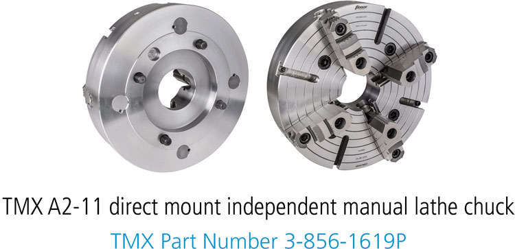
Spindle Type and Size Guide
Common Machine Spindle Types

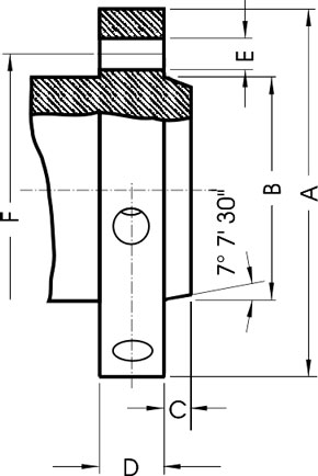
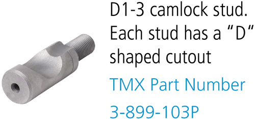
Determining D1 Type Spindle and Size
Measure the pilot diameter and length (B & C)
Measure the bolt circle diameter (F)
Measure the diameter of the holes (E)

|
Spindle |
A |
F |
B |
C |
E |
Number |
Camlock |
|
D1-3 |
3.622 |
2.7820 |
2.1250 + .00025 |
.4375 |
.5937 |
3 |
9/16 |
|
D1-4 |
4.606 |
3.2500 |
2.5005 + .0005 |
.4375 |
.6562 |
5/8 |
|
|
D1-5 |
5.748 |
4.1250 |
3.2505 + .0005 |
.5000 |
.8750 |
6 |
3/4 |
|
D1-6 |
7.126 |
5.2500 |
4.1880 + .0005 |
.5625 |
1.000 |
7/8 |
|
|
D1-8 |
8.858 |
6.7500 |
5.50075 +.0005 |
.6250 |
1.125 |
1 |
|
|
D1-11 |
11.732 |
9.2520 |
7.75075 +.0005 |
.6875 |
1.250 |
1 3/16 |
|
|
D1-15 |
15.866 |
13.0000 |
11.251 + .001 |
.7500 |
1.375 |
1 3/8 |

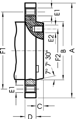
Determining an A Type Spindle and Size
- Measure the pilot diameter and length (B & C)
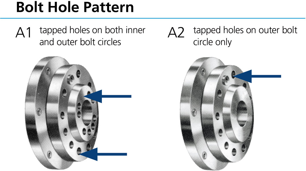
- Measure the bolt circle diameter (F1 and F2) and diameter of the holes (E1 & E2)
- Check the number of bolt circles (one for A2 mount or two for A1 mount)
- All chucks with A1 mount can be installed on A1 spindle nose only
- All chucks with A2 mount can be installed on either a A2 or A1 spindle.

|
Spindle |
F1 |
F2 |
B |
C |
Thread |
|
A-4 |
3.2500 |
- |
2.5005 + .0005 |
.4375 |
7/16-14 |
|
A-5 |
4.1250 |
2.4374 |
3.2505 +.0005 |
.5625 |
7/16-14 |
|
A-6 |
5.2500 |
3.2500 |
4.1880 + .0005 |
.6250 |
1/2-13 |
|
A-8 |
6.7500 |
4.37500 |
5.50075 + .0005 |
.6875 |
5/8-11 |
|
A-11 |
9.2500 |
6.5000 |
7.75075 + .0005 |
.7500 |
3/4-10 |
|
A-15 |
13.0000 |
9.7500 |
11.251 + .001 |
.8125 |
7/8-9 |
|
A-20 |
18.2500 |
14.5000 |
16.251 +.001 |
.8750 |
1-8 |
|
A-28 |
25.5000 |
20.8750 |
23.001 + .001 |
1.000 |
1 1/4-7 |
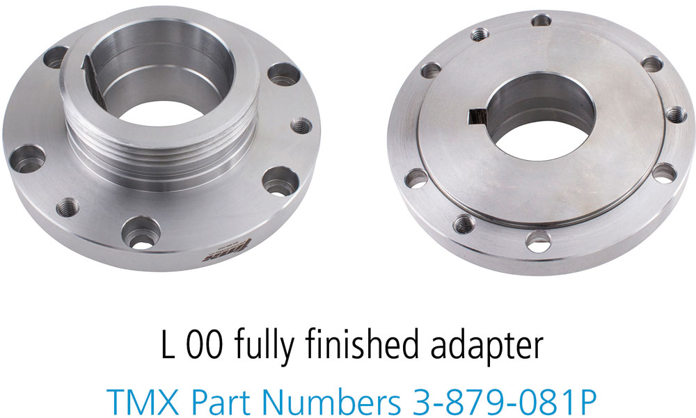
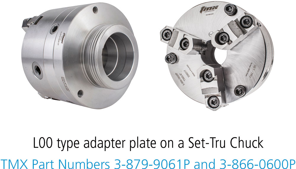
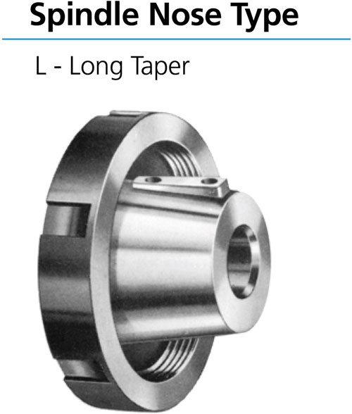
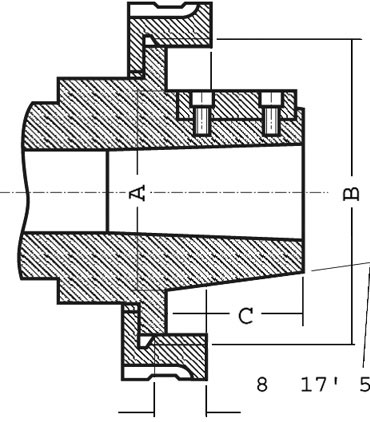
Determining an L Type Spindle and Size
- Measure pilot diameter (A)
- Measure length (C)
- Measure thread size (dimension B)
|
Spindle |
Thread |
C |
A |
Key |
|
L00 |
3 3/4" - 6" |
2 |
2.750 |
3/8 x 3/8 x 1 1/2 |
|
L0 |
4 1/2" - 6" |
2 3/8 |
3.250 |
3/8 x 3/8 x 1 3/4 |
|
L1 |
6" - 6" |
2 7/8 |
4.125 |
5/8 x 5/8 x 2 3/8 |
|
L2 |
7 3/4" - 5" |
3 3/8 |
5.250 |
3/4 x 3/4 x 2 7/8 |
|
L3 |
10 3/8" - 4" |
3 7/8 |
6.500 |
1 x 1 x 3 1/4 |